Rochdale Olympic phase 1, front suspension.


The front suspension on the phase 1 Olympic is derived from either the Riley 1.5/Wolseley 1500, or the Morris Minor. Both types are effectively the same however there are subtle differences which are covered below.


The front upright/kingpin of the Riley/Wolseley and Morris Minor differ in the positioning of the steering arm which is also different. The Riley/Wolseley steering arm is positioned on the top steering arm boss, whereas the Morris Minor steering arm is fitted to the bottom steering arm boss on the upright.

The diameter of the torsion bars also differs dependent on the model they originate from. The difference from model to model is in the core diameter of the torsion bar, the length and spline fitting is the same across the whole range of models using this set up, they are therefor interchangable.


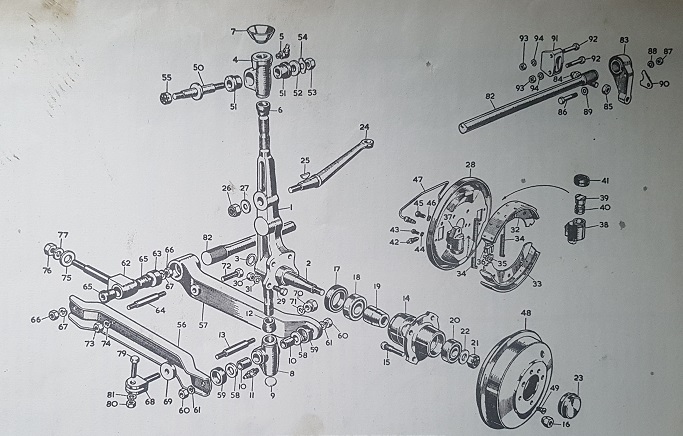
1. Kingpin and stub axle.

2. Stub axle.

3. Circlip.

4. Upper link.

5. Grease nipple for upper link.

6. Rubber seal.

7. Top plate.

8. Lower link.

9. Plug.

10. Bush.

11. Grease nipple for lower link.

12. Rubber seal.

13. Lower link fulcrum pin.

14. Hub assembly.

15. Wheel stud.

16. Nut for wheel stud.

17. Hub oil seal.

18. Inner bearing.

19. Bearing distance piece.

20. Outer bearing.

21. Nut-LH thread.

22. Washer for nut.

23. Cap.

24. Steering arm left hand.

25. Key to swivel pin.

26. Nut for swivel pin.

27. Washer for nut.

28. Brake plate left hand.

29. Brake plate to swivel pin bolt.

30. Nut for bolt.

31. Spring washer.

32. Brake shoe assembly.

33. Brake lining.

34. Shoe pull off spring.

35. Brake adjuster.

36. Mask adjuster.

37. Wheel cylinder LH.

38. Body LH.

39. Piston.

40. Taper seal.

41. Rubber boot.

42. Blead screw.

43. Wheel cylinder bolt SM.

44. Spring washer.

45. Wheel cylinder bolt LG.

46. Spring washer.

47. Bridge pipe.

48. Brake drum.

49. Screw-drum to hub.

50. Damper arm pivot bolt.

51. Rubber bush for upper link.

52. Washer for rear pivot.

53. Nut for rear pivot.

54. Tab washer for rear pivot.

55. Nut for front pivot.

56. Wishbone arm front.

57. Wishbone arm rear.

58. Thrust washer for link fulcrum pin.

59. Sealing ring for link fulcrum pin.

60. Nut for link fulcrum pin.

61. Spring washer.

62. Eye bolt.

63. Spigot pivot rear.

64. Fulcrum pin.

65. Rubber bush for eye bolt.

66. Nut.

67. Spring washer.

68. Wishbone fork.

69. Washer.

70. Fork nut.

71. Spring washer.

72. Bolt front to rear arm.

73. Nut.

74. Spring washer.

75. Eye bolt lock washer.

76. Nut.

77. Washer.

79. Anti roll bar to fork bolt.

80. Nut.

81. Spring washer.

82. Torsion bar.

83. Torsion bar lever.

84. Torsion bar adjuster.

85. Locknut.

86. Not used on Olympic.

87. Not used on Olympic.

88. Not used on Olympic.

89. Not used on Olympic.

90. Not used on Olympic.

91. Abutment bracket.

92. Bolt.

93. Nut.

94. Washer.


Front suspension general

The front suspension is independent type consisting of the built-up lower wishbone. Longitudinal torsion bar, and a single upper link which attatches to the Armstrong double acting lever-arm type hydraulic damper, this acts as the upper link for the front suspension. the torsion bars are attached to the shell of the car in the cockpit area on a moulded transverse mounting. The torsion bar mounting and adjuster being held in place on a fabricated mounting plate attached to the transverse moulding and is adjusted by means of a threaded bolt which pushes against a stop (abutment bracket) mounted on the plate.


The front of the torsion bar is fitted into a splined hole at the inner end of the two piece bottom wishbone and also acts as a pivot for the bottom wishbone. The inner pivot rotates around the eyebolt which is in turn attached to the bottom mounting of the fabricated tubular front subframe. The lever arm damper/top wishbone is also attached to the fabricated subframe on a plate and secured by means of 4 high tensile bolts and lock nuts. The steering rack is mounted on the front subframe, the mounting of the steering rack will differ dependent on which car the front suspension component are derived from, this will be explained in later sections of this manual.


Front suspension - Maintenance

The six grease nipples on the front suspension should be greased at intervals of 3,000 miles with a grease gun filled with Castrolease L. M. or similar. The grease nipples are located as follows:- One on each steering track rod end, total two. One at the top and bottom of each stub axle assembly/kingpin, four in total.


When lubricating the stub axle nipples jack the front of the car up to take the weight off the king pins.


At intervals of 6,000 miles thoroughly clean the area around the damper filler plug, unscrew the plug and check the level of the hydraulic fluid which should be just below the filler plug threads. Replenish the damper as necessary with Armstrong super thin shock absorber oil, or any good quality mineral oil of S.A.E 20/20W specification.


Front suspension - Strip

Jack up the front of the car and support on suitable axle stands or similar. these should be placed under the body of the car (with a 12" x 12" thick wooden plate to spread the loading) at the point where the inner footwell vertical moulding, the inner engine bay moulding and the floor intersect. Remove the front wheels and place under the car or in a suitable place for safe storage.


With the weight off the car, remove the anti roll bar from the bottom wishbones on both sides of the car by undoing and removing the bolt on the fork which passes through the anti roll bar bush. The anti roll bar is fastened to the bottom wishbone with a through bolt on a fork fitted through the two part bottom wishbone, with the anti roll bar free of this fork the front suspension is now free to move independently without effecting the suspension on the opposite side. It is now necessary to remove the spring tension from the torsion bar, this is done by means of the adjusters inside the cockpit on the transverse moulding just in front of the driver, and passenger seats. Screw the adjusting bolt fully in, this will release the tension on the torsion bar itself, it should now be possible to lever/push the adjusting cam onto the torsion bar off the splines which hold it in place. With the back of the torsion bar free you should be able to remove the bar from the spline on the bottom wishbone, the torsion bar now can now be removed from inside the car through the hole in the inner footwell.


With all the weight off the car the next step is to remove the kingpin/upright from the car. Undo the nut on the track rod end and with a suitable joint remover take the track rod end off the steering arm and position it out of the way. It is now necessary to remove the flexible brake hose from the fitting on the inner engine bay panel by undoing the solid copper brake pipe from the bulkhead fitting and taking that fitting off the inner bulkhead. Now undo the 3/8" UNF nuts from either side of the bottom trunnion, next remove the anti roll bar fork which fits through the front and rear bottom wishbones, and remove the 3/8" UNF nut on the front side of the eyebolt which holds the inner wishbones in place on the front sub frame. The pressed steel lower wishbone can now be removed which will allow the bottom trunnion pivot pin to slide off the trunnion releasing the bottom of the kingpin/upright from the bottom wishbone. Now undo and remove the 1/2" UNF (possibly UNC) nut from the top wishbone/lever arm damper which holds the top trunnion, it should now be possible to remove the kingpin from the car complete with the front hubs and brakes.


Remove the lever arm damper from the front subframe by undoing the four 5/16" UNF nuts and bolts holding it on the mounting plate.


The inner bottom cast wishbone can now be removed from the subframe. Undo the 1/2" UNF nut on the inside of the eyebolt which holds it onto the subframe the eyebolt can now be rotated to allow the bottom wishbone to be withdrawn from the eyebolt.


Front hub removal and replacement

The front hubs are not adjustable and if wear is detected (play between the road wheel and backplate) the hubs will have to be removed and new bearings fitted. A hub extractor/3 leg puller is required for this job.


Jack up the front of the car and support on suitable axle stands or similar. these should be placed under the body of the car (with a 12" x 12" thick wooden plate to spread the loading) at the point where the inner footwell vertical moulding, the inner engine bay moulding and the floor intersect. Remove the front wheels and place under the car or in a suitable place for safe storage.


Unscrew the brake drum retaining screws and pull off the brake drum.


Lever off the hub cap, extract the split pin, unscrew and remove the castellated nut and locating washer.


Use the hub extractor to pull the complete hub assembly off the stub axle. If the inner bearing remains on the stub axle shaft it must be pulled off the stub axle with a suitable bearing puller. Frequently the inner race of the inner bearing is left in place on the stub axle, if this happens it is often easiest to remove the brake back plate assembly on drum braked cars to ease the removal of the inner bearing race.


Carefully tap out the distance piece and outer bearing with a suitable drift, and then drift out the inner bearing and oils seal from the inside of the hub. The hub is now completely dismantled.


Replacement is a direct reversal of the removal sequence but the following points should be noted.


The bearings and the space between them must be lubricated with a suitable LM grease.


The sides marked thrust on the inner and outer bearings must face towards the bearing distance piece.


The oil lip seal should face the inner bearing.


The castellated nut should be tightened to 55lb/in to 65lb/in.


Finally wipe away any exess grease and half fill the hub retaining cap.


Stripping down the front kingpins

Jack up the front of the car and support on suitable axle stands or similar. these should be placed under the body of the car (with a 12" x 12" thick wooden plate to spread the loading) at the point where the inner footwell vertical moulding, the inner engine bay moulding and the floor intersect. Remove the front wheels and place under the car or in a suitable place for safe storage.


To remove and replace the bottom trunnion it is first necessary to remove the front hub as described above. With the front hub removed undo the 4 retaining bolts from the brake backplate and remove it, if it is still attached to the car by the flexible brake hose you can support it out of the way using a suitable piece of wire to hold it thus relieving any stress on the flexible brake hose. It is now necessary to undo the two nuts either side of the bottom trunnion. The front pressed steel part of the two piece bottom wishbone can now be removed using the method described above. The pivot pin for the bottom trunnion can now be removed,

Note

due to its construction it is not possible to unscrew the bottom trunnion pin from the kingpin without removing the pin first, if you don't remove the pin before undoing the trunnion irreparable damage will be done to the kingpin.


The bottom trunnion can now be removed, this is achieved by unscrewing the trunnion on the kingpin thread, this will either be a left hand or a right hand thread dependent on which side of the car it s attached to.


To remove and replace the top trunnion undo the 1/2" UNF nut from the lever arm damper, dependent on the type of nut used it may be necessary to remove the split pin from the castellated nut first. Remove the large washer from the lever arm/trunnion mounting pin and using a suitable lever remove the top trunnion from the lever arm/trunnion mounting pin, during this operation support the top of the kingpin as when the trunnion is removed the kingpin will be free to rotate about the bottom trunnion. Now unscrew the trunnion from the kingpin, as with the bottom trunnion the threads are either left or right hand dependent on the side of the car you are working on.


Replacement of both the top and bottom trunnions is a direct reversal of the procedure used to remove them, however it is necessary to make sure there is enough thread allowance to stop the kingpin locking up when the steering lock is applied. This is achieved be screwing the trunnion all the way onto the kingpin, once it has stopped turning i.e. it is fully home on the kingpin threads undo the trunnion so that it is in the correct position to refit, from this position undo the trunnion a further turn then refit. This will allow the steering to operate as designed and also give the trunnion the maximum amount of thread engagement to allow for safe use.


The rest of the rebuild procedure can now be carried out. Once the front suspension is built up and everything is working as it should grease all the suspension using a suitable HMP grease.


----------------------------
Copyright © Rochdale Owners Club
Last Update